Here's a quote from an older post on tapping a relay:
So... IMHO, the best location to tap switched power on the FZ6R is the Licence Plate Light bullet connector under the Right Rear Panel.
To access the connector (as well as the taillight and signal light connectors):
1. Remove Rear Seat
2. Remove the Grab Rail (4 bolts. You can get away with just removing the right 2 bolts and flexing the grab rail out of the way when removing the panel.)
3. Remove the Right Rear Side Panel (3 plastic rivets)
4. Roll the rain boot forward out of the way (or pop out the wire clip and slide the rain boot forward.)
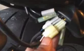
5. You now have full access to the tail lighting connectors:
A 3 Position 090 HM Connector (Wires: Yellow = Brake Light, Blue = Tail Light, Black = Ground)
A Black Nippon -Tanshi’s 3P Turn Signal Connector (Wires: Brown = Left Signal Light, Black = Ground)
A Grey Nippon -Tanshi’s 3P Turn Signal Connector (Wires: Green= Right Signal Light, Black = Ground)
2 Bullet connectors, 1 with Blue wire in and black wire out (positive), the other with Black Ground wires.
6. Disconnect Bullet Connector with Blue wire.
7. Connect split lead (photo coming) between male and female bullets.
8. Route the switched power wire to the location/device required.
9. Replace Rain Boot, Side Panel and Grab Rail and all fasteners.