UselessPickles
New Member
We were, but then this happened:I thought we were talking about the throttle position sensor, not the tach.
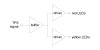
As for the throttle signal, it's pretty easy. Just splice a wire into the TPS wire somewhere, connect it to an analog input pin of the hardware, and now you can read the throttle position as a number ranging from 0 to 1023 (assuming 10-bit ADC, which is common).I would look into sensing the tachometer output with one of the A/D channels, then you can drive your LEDS with one/many digital outputs.
The catch is that the TPS signal does not cover the whole range of 0-5 volts. You have to calibrate the TPS signal somehow so that your code knows that, for example, 0% throttle is a digital value of 117 and 100% throttle is a digital value of 723. The exact range will vary from bike to bike (this is why you need to calibrate the throttle for a Power Commander).
I included some calibration code in my device that runs upon startup if there is a throttle reading over 512 for a full second. It stores the highest value read as the max throttle position. Then it waits for the throttle to drop below 512 for a full second and records the lowest value read. Some basic math can then convert any raw throttle position reading into a value ranging between 0 and whatever I want to use as my max throttle value.
That's once place where microcontroller programming becomes fun. You want to avoid floating point math if at all possible because they have no hardware floating point math support. The compiler will happily allow you to using floating point math, but it is all done in software. this means that a large chunk of your precious limited program memory on the chip is now used up with all the code necessary to perform floating point math operations. So you try to stick to integers. If you need more precision than whole numbers, then you can use integers as "fixed point" numbers and deal with the complications of fixed point integer math, including the limited sizes of integers. You have to be careful to ensure that the numbers you will be working with will not overflow when multiplying, etc.